Material Properties in SpeedCast
In
SpeedCast we use two material properties that you have never seen before. Cutting Stiffness and
Process Damping Wavelength. Together we often refer them as the Force Model.

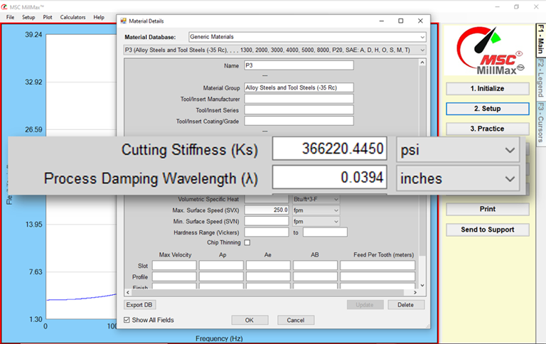
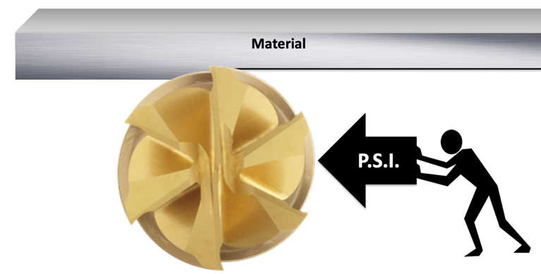
Cutting Stiffness is
the amount of force it takes for the cutter to cut through that particular
material. It is measured in Newtons per Square Millimeter or Pounds per Square
Inch (PSI).

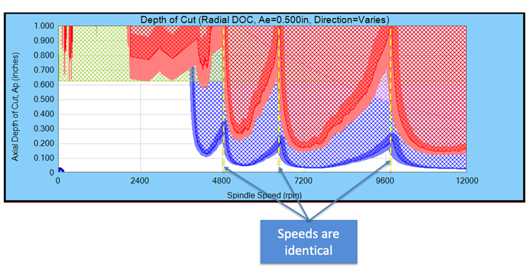
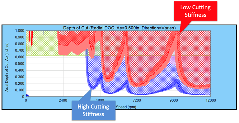
A high
cutting stiffness is shown in blue and a low cutting stiffness in shown in red.
High cutting stiffness limits the depth of cut.

Note, that though the
depth of cut is limited the stable speeds are identical regardless of the
material.

The
Cutting Stiffness can also change by the direction of the cutting force of the
milling tool.
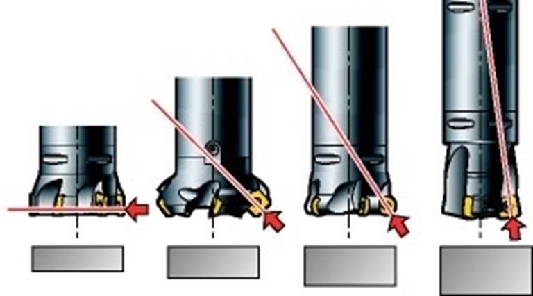
With 90
degree mills the cutting force is radial. Feed mills move the majority of the
cutting force axially.
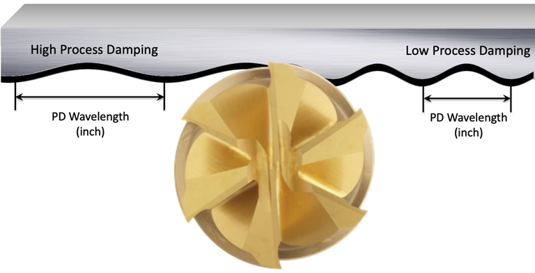
Process Damping
Wavelength is the amount of vibration energy that is absorbed,
primarily by the geometry of the cutter. Process damping is measured by the
length of the wave. The longer the wave, the less it vibrates.
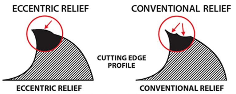
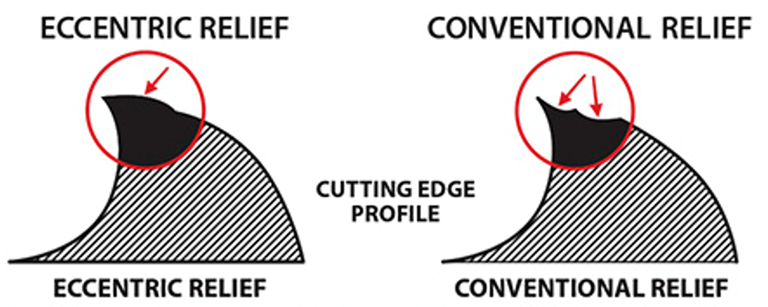
Edge
prep or eccentric relief increases Process Damping.
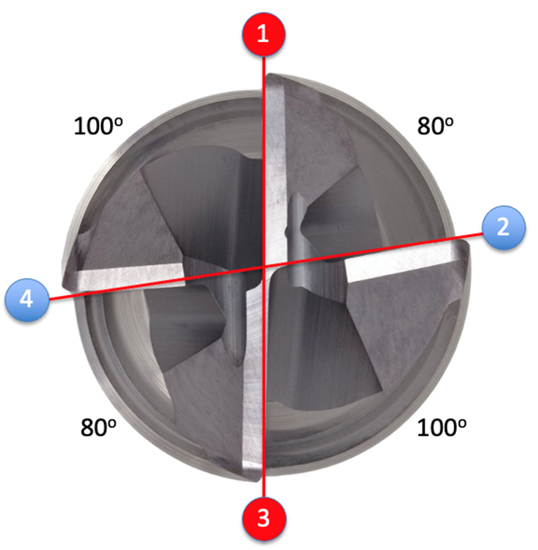
Perhaps
the largest source of Process Damping is variable pitch endmills. Tooth 1 and 3
are doing most of the cutting. Tooth 2 and 4 are followers and act like shock
absorbers.
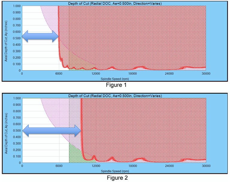
Process Damping
increases the low-speed stable range. Figure 2 has higher Process Damping than
Figure 1.

Because
we could not possibly know the exact properties of every material and the
process damping of every cutter/material combination we have to make
assumptions. Sometimes, when tapping an existing tool and material that a customer
has had years or months of trial-and-error adjustments, the resulting dashboard
shows red where the customer is currently stable. We can calibrate the Cutting
Stiffness and Process Damping to the known stable condition and then optimize
the process.
SpeedCast の材料特性
SpeedCastでは、これまでに見たことのない2つのマテリアルプロパティを使用しています。
切削剛性とプロセス減衰波長 私たちはそれらを一緒に、フォースモデルと呼ぶことがよくあります。

切削剛性とは、カッターがその特定の材料を切断するのに必要な力の量です。これは、ニュートン/平方ミリメートルまたはポンド/平方インチ
(PSI) で測定されます。

高い切削剛性は青色で示され、低い切削剛性は赤色で示されます。切削剛性が高いと、切込みの深さが制限されます。

切込み深さは制限されていますが、安定した速度は材料に関係なく同じであることに注意してください。
切削剛性は、フライス工具の切削抵抗の方向によっても変化する可能性があります。

90度ミルでは、切削抵抗は半径方向です。フィードミルは切削抵抗の大部分を軸方向に動かします。
プロセス減衰波長は、主にカッターの形状によって吸収される振動エネルギーの量です。プロセス減衰は、波の長さによって測定されます。波が長ければ長いほど、振動は少なくなります。

エッジの準備または偏心リリーフにより、プロセスダンピングが増加します。
おそらく、プロセス減衰の最大の原因は可変ピッチエンドミルです。歯 1 と 3 がほとんどの切断を行っています。歯
2 と 4 はフォロワーであり、ショックアブソーバーのように機能します。

プロセスダンピングにより、低速安定範囲が増加します。図 2 は、図 1 よりもプロセス
ダンピングが高くなります。
すべての材料の正確な特性と、すべてのカッター/材料の組み合わせのプロセス減衰を知ることは不可能であるため、仮定を立てる必要があります。顧客が数年または数か月にわたって試行錯誤の調整を行った既存の工具や材料をタップすると、結果のダッシュボードに、顧客が現在安定している場所が赤色で表示されることがあります。切削剛性とプロセス減衰を既知の安定した状態に調整し、プロセスを最適化できます。
Materialeigenschaften in
SpeedCast
In
SpeedCast verwenden wir zwei Materialeigenschaften, die
Sie noch nie zuvor gesehen haben.
Wellenlänge der Schnittsteifigkeit
und Prozessdämpfung. Zusammen bezeichnen wir sie oft als das Kraftmodell.
Die Schnittsteifigkeit ist die Kraft, die der Fräser benötigt,
um durch dieses bestimmte
Material zu schneiden. Es wird in Newton pro Quadratmillimeter
oder Pfund pro Quadratzoll
(PSI) gemessen.
Eine hohe Schnittsteifigkeit ist in blau und eine niedrige Schnittsteifigkeit
in rot dargestellt. Eine hohe
Schnittsteifigkeit begrenzt
die Schnitttiefe.
Beachten Sie, dass die Schnitttiefe zwar begrenzt ist,
die stabilen Geschwindigkeiten
jedoch unabhängig vom Material identisch sind.

Die Schnittsteifigkeit kann sich auch durch
die Richtung der Schnittkraft
des Fräswerkzeugs ändern.

Bei
90-Grad-Fräsern ist die Schnittkraft
radial. Vorschubmühlen bewegen
den Großteil der Schnittkraft
axial.
Die Wellenlänge
der Prozessdämpfung ist
die Menge an Schwingungsenergie, die hauptsächlich von der Geometrie
des Fräsers absorbiert wird. Die Prozessdämpfung wird durch die Länge der Welle gemessen. Je länger die Welle, desto weniger schwingt sie.

Die Kantenvorbereitung oder Exzenterentlastung erhöht die Prozessdämpfung.

Die vielleicht größte Quelle für Prozessdämpfung sind Schaftfräser mit variabler Steigung. Zahn 1 und 3 erledigen den größten Teil des Schnitts. Zahn 2 und 4 sind Mitnehmer und wirken wie Stoßdämpfer.

Die Prozessdämpfung
erhöht den stabilen Bereich bei niedrigen
Drehzahlen. Abbildung 2 weist eine höhere
Prozessdämpfung auf als Abbildung 1.

Da wir unmöglich die genauen Eigenschaften jedes Materials und die Prozessdämpfung
jeder Fräser-Material-Kombination
kennen können, müssen wir Annahmen
treffen. Manchmal, wenn ein vorhandenes
Werkzeug und Material angetippt
wird, das ein Kunde jahre- oder monatelang
durch Versuch und Irrtum angepasst hat, zeigt das resultierende Dashboard
rot an, wo der Kunde derzeit stabil
ist. Wir können die Schnittsteifigkeit und die Prozessdämpfung
auf den bekannten stabilen Zustand kalibrieren und dann den Prozess optimieren.